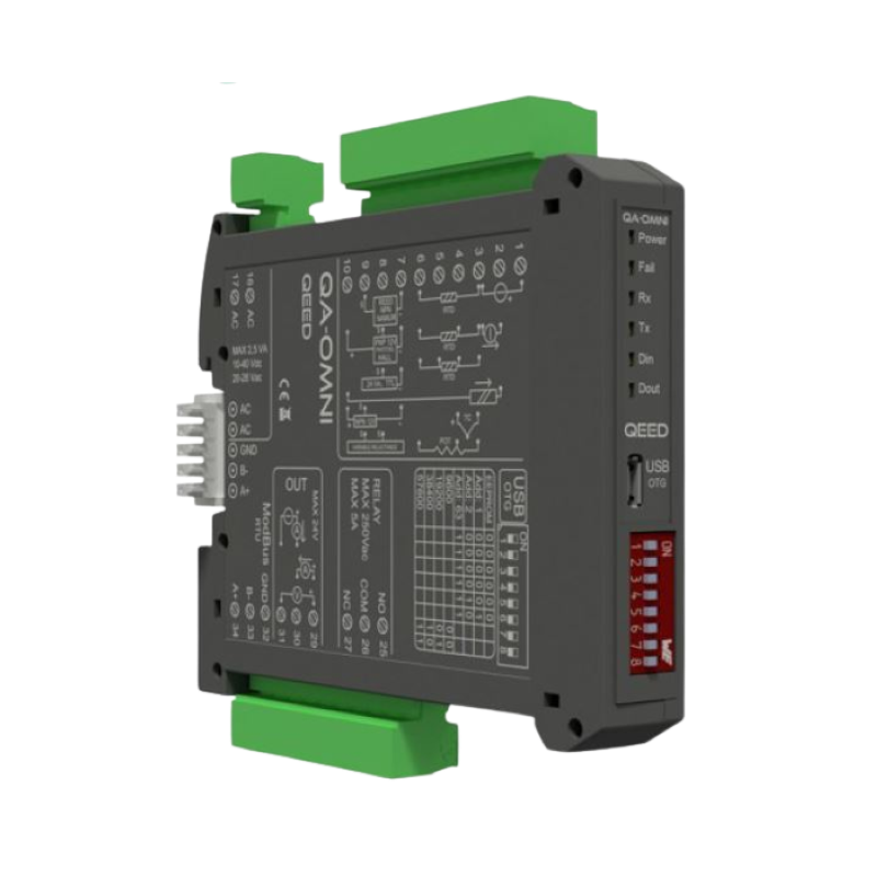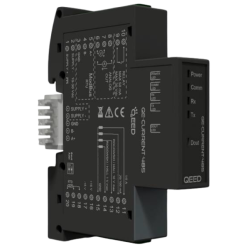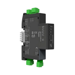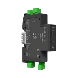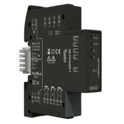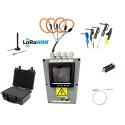
QEED QA-OMNI UNIVERSAL SIGNAL CONVERTER
Delivery:
Advanced UNIVERSAL SIGNAL CONVERTER, USB configurable, DIN rail mounting, 4-way galvanically isolated, universal power supply AC/DC, Programmable alarm contact, RS485 Modbus.
DATALOGGING via USB with pen drive stick memory and download storage data on excel importable files. RTC Real Time Clock integrated. CURRENT, VOLTAGE, FREQUENCY,
POTENTIOMETER, TEMPERATURE (RTD and TC all types).
Related Products

VOLTAGE:
up to 10 Vdc programmable, input impedence 100 KOhm, 1mV
resolution.
CURRENT:
up to 20 mA programmable, input impedence 20 Ohm, max resolution
2μA.
TEMPERATURE:
RTD: Pt100, Pt500, Pt1000, Ni100. 2,3 or 4 wire measure, automatic
detection of cable interruption.
TC Types: J, K, R, S, T, B, E, N; automatic detection of cable interruption
(-10mV to 70mV).
POTENTIOMETER: from 1000 Ohm to 10 KOhm.
FREQUENCY:
from 0,001 Hz to 9,99KHz, mechanical contact, npn 2 and 3 wires, pnp 3
wires with supply of 24 Vdc, namur, photoelectric, Hall sensor, variable
reluctance, pulse 24 V, TTL.PR SUPPLY
Power Supply: TECTION INDEX
10..40 Vdc, 20-28 Vac, 50-60 Hz
RETRASMISSION OUTPUT:
One isolated analog output,
Voltage and Current (impressed) programmable; Active
or Passive supply output (13 Vdc, 30mA max)
ABSOPRPTION:
Maximum 2,5 VA
Protection Degree:
IP20
ACCURACY :
0.1% Full Scale
RESOLUTION:
16 bit (15 + sign for TC)
REJECTION:
50-60 Hz
THERMAL STABILITY AT 25°C:
< 100 ppm/°C
WORKING TEMPERATURE:
-15...+65°C
STORAGE TEMPERATURE:
-40°C... +85°C
ISOLATION:
Input, analog and digital output,
serial output RS485 and USB port, Power supply, are
4-way galvanically isolated at 1,5kV
HUMIDITY: CCURACY
10...90% non condensing O
ALTITUDE:
Up to 2000 m s.l.m.
MOUNTING:
DIN rail mounting with removable
terminals, RS485 bus and Supply connection ready on
the base of module (connector not included, on request).
CONNECTIONS:
Removable terminals 5,08mm
CE STANDARDS:
EN61000-6-4/2006 + A1 2011;
EN64000-6-2/2005; EN61010-1/2010
DIMENSIONS:
17,5 x 100 x 112 mm (terminals excluded)
DATA LOGGER:
Non-volating memory. Log on USB
OnTheGo port by Pen Drive stick memory. The software
FACILE QA-OMNI (free of charge) allow you to configure
Log, all conversion parameters, set contact alarm, set
Modbus address. RTC Real Time Clock integrated
CONFIGURATION:
By free software FACILE QA-OMNI to configure all of the
conversion parameters like span, zero, alarm contact and
log via USB port or via RS485. Dip-switch for setting
modbus address and baudrate
ELECTRICAL CONNECTIONS:
POWER SUPPLY:
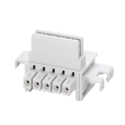
10...40 Vdc or 20...28 Vac - Connectors 16 and 17, or by T-BUS connector (optional tool) on the base of the module (see the picture placed on the bottom of this page).
ANALOG INPUT:
depending on the type of sensor or signal available, make the connection as shown. For example, to connect a 3-wire RTD sensor requires a connection to terminals 3, 4 and 6. The Thermocouple, whatever it is, it requires the connection between terminals 3 and 4.
To connect a potentiometer use terminals 3, 4 and 6.
To make resistance measurements at 2, 3 and 4 wires to follow the wiring diagram for the RTD.
For ACTIVE current input use the connectors 2 (positive) and 3. For PASSIVE current input use connectors 2 (positive) and 10 . For Voltage input use connectors 1 (positive) and 3.
DIGITAL INPUT:
the QA-OMNI accepts the input pulses from 0,001 Hz to 9,99 KHz, from mechanical contact, NPN 2 and 3 wire, PNP 3-wire with power supply 24 Vdc, namur, photoelectric sensor, Hall, variable reluctance, pulse 24 V, TTL.
For the connection, refer to the diagram as shown.
ANALOG OUTPUT:
for Voltage analog output, connect terminals 31 and 29 (positive).
For ACTIVE current analog output, connect terminals 29 (positive) and 30. For PASSIVE current analog output, connect terminals 30 (positive) and 31. Analog output supply: 13 Vdc, max 30mA.
DIGITAL OUTPUT:
relay Output SPDT. Connect terminal 25 for Normally Open mode, terminal 26 for Normally Close. The default setting is Normally Open (NO).
SERIAL OUTPUT RS485:
available on connectors 32, 33 (B-), 34 (A+), or by T-BUS connector to be mounted on the module
T-BUS CONNECTION (OPTION), needs T-BUS connector:
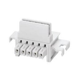
It may be affixed to the accessory T-BUS based on the module to bring both power and serial communication. The number of modules supported by the bus is a function of the power supply used (check the absorption of the modules).

- chevron_left
- 1
- chevron_right
Your review appreciation cannot be sent
Report comment
Report sent
Your report cannot be sent
Write your review
Review sent
Your review cannot be sent

